VCU’s Microcomputer Systems course taught me how to program, analyze, and debug a microprocessor using assembly language and the C programing language. It also exposed me on how to interface sensors as well as input/output devices to a microprocessor. It helped in understanding the concept of an instruction set architecture and the major hardware and software components of a microcomputer.
Abstract
This project consisted of designing and implementing an embedded system. An autonomous robot that is capable of navigating through a maze, follow a black line drawn on a white surface, and draw a visually appealing image on a canvas all using the knowledge and techniques acquired throughout this course. The project deliverables, timelines, constraints, and how each feat was implemented can be easily followed throughout the page.

Mechanical Design
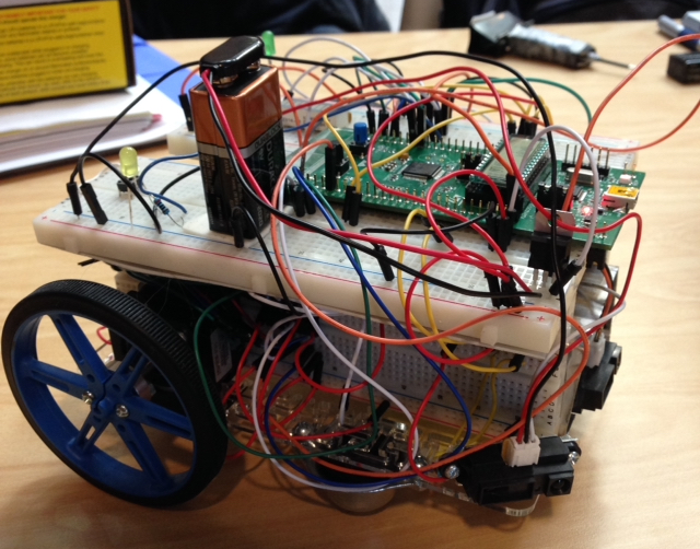
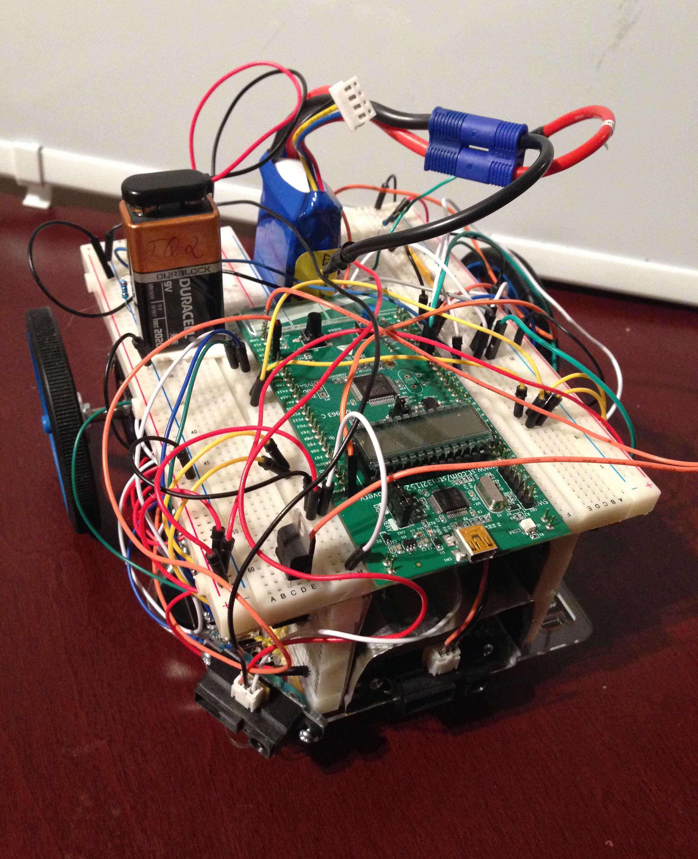
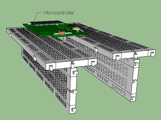
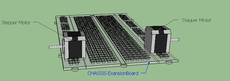
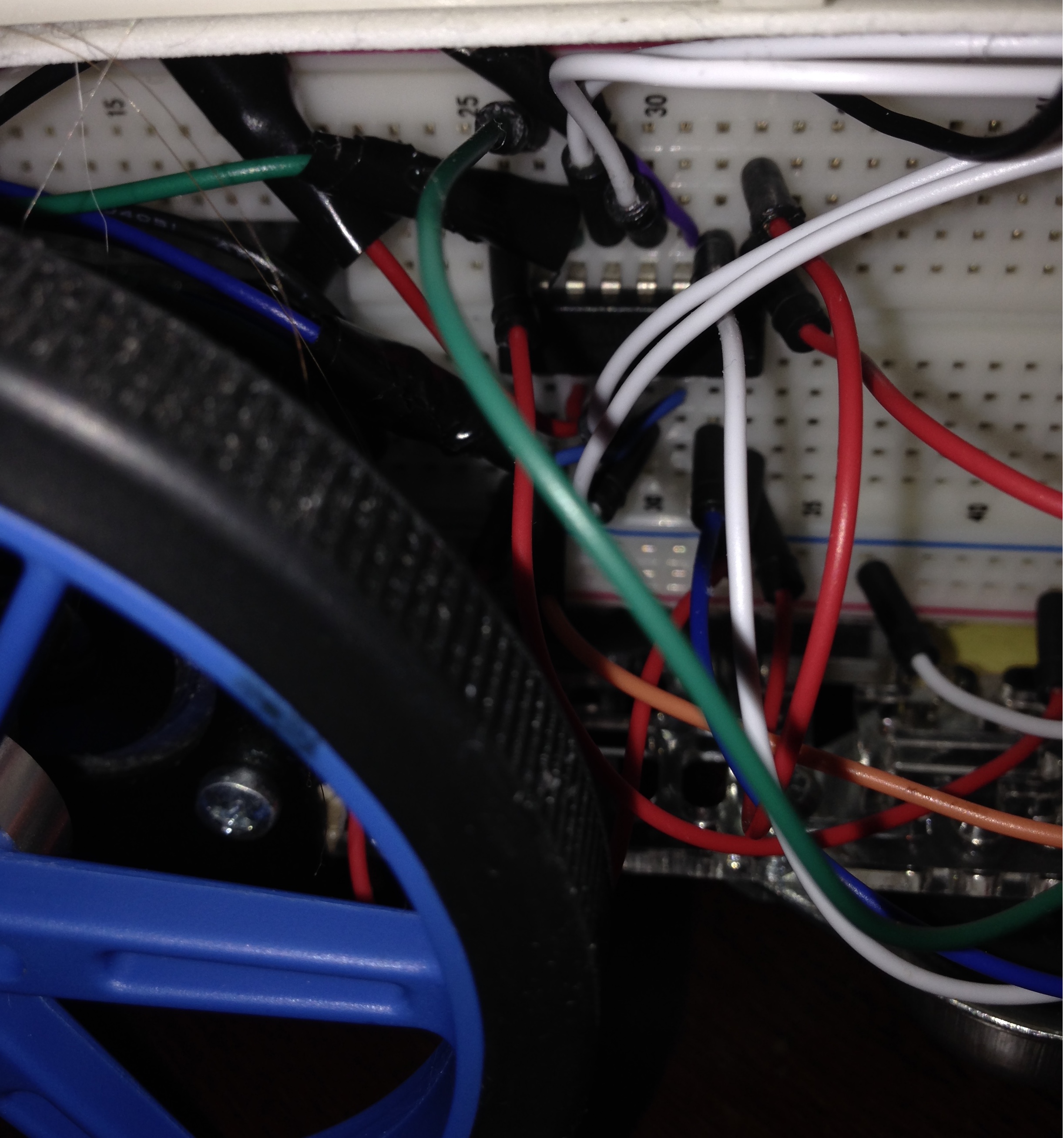
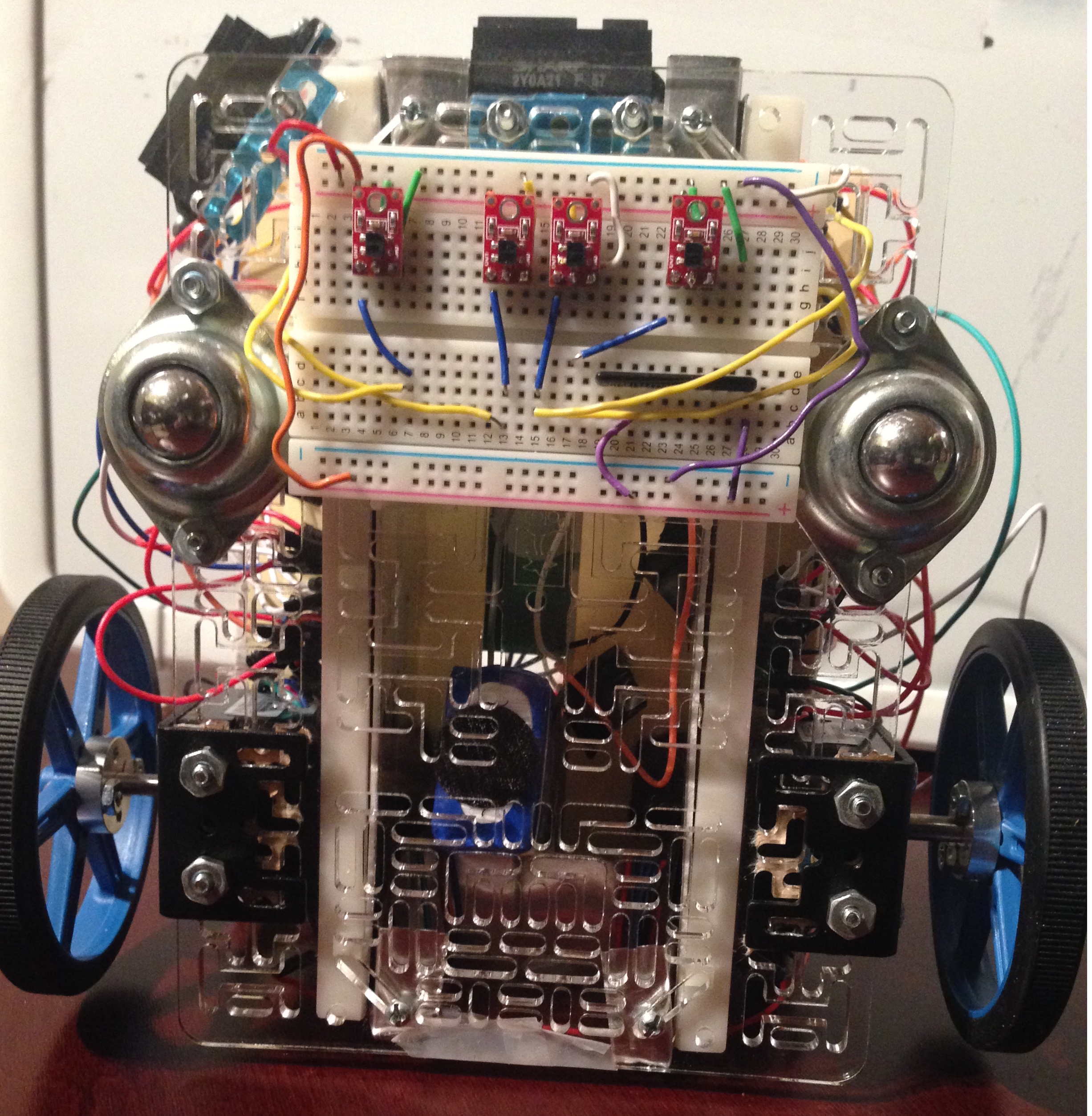
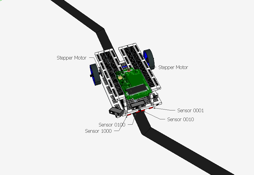
For the base of the Robot an acrylic glass expansion plate with all the mounting holes necessary was used that allowed for the design to have many configurations. For the rest of the chassis, four breadboards where use as the structure of the robot which are bridged by the microcontroller on top as seen below. The two breadboards on the sides, allowed for easier connections to the H-bridges* and stepper motors. This helped organize the wire clutter and allowed for a more manageable system that was easy to troubleshoot.
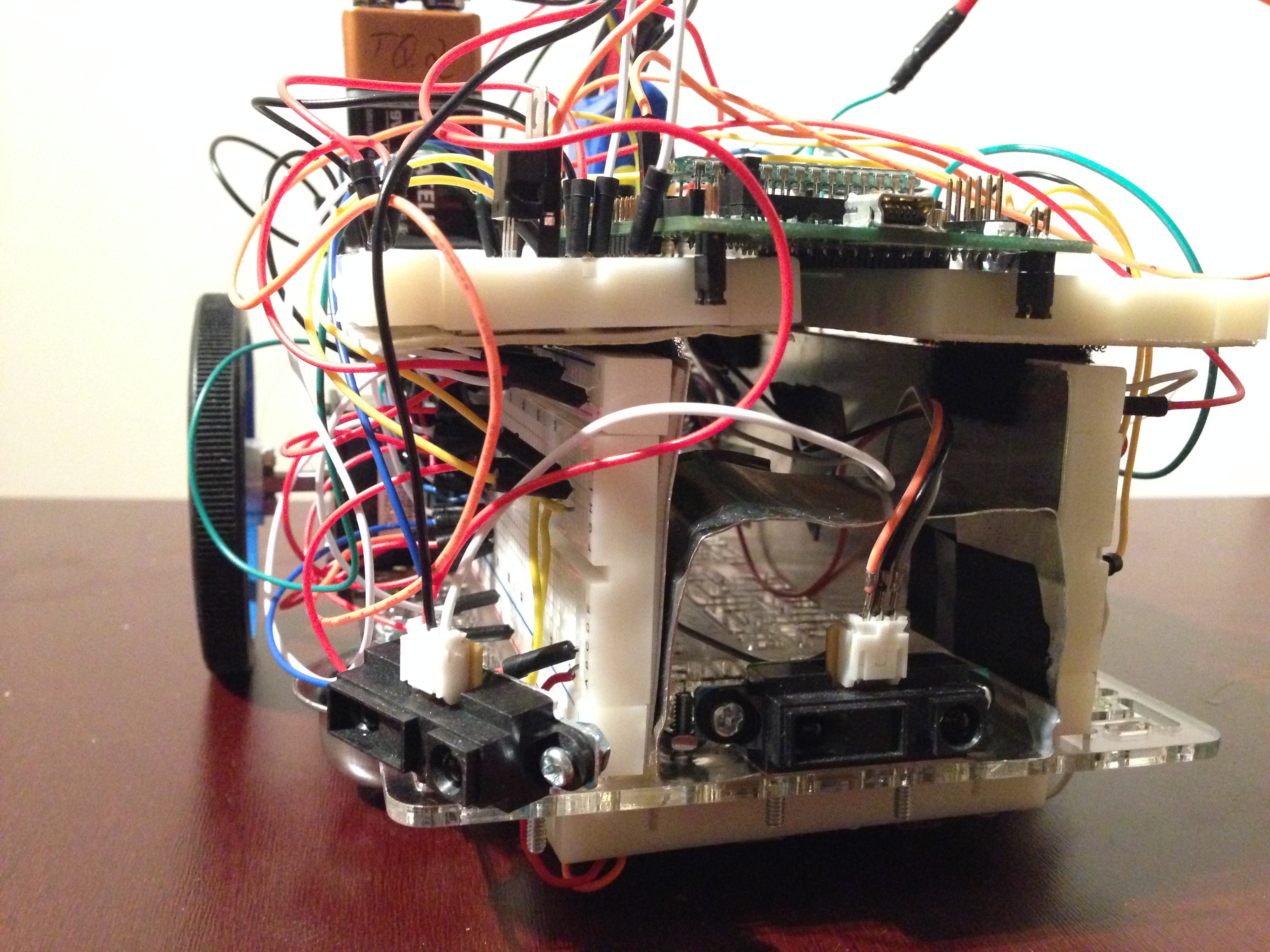
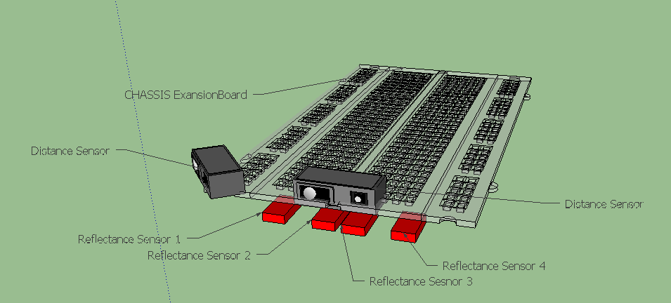
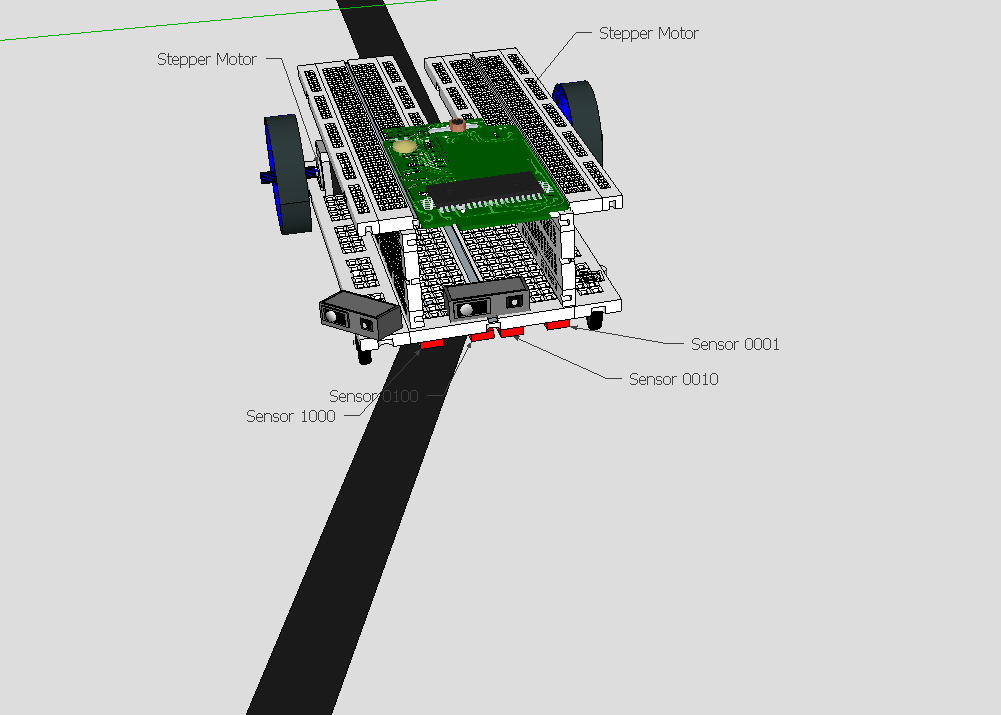
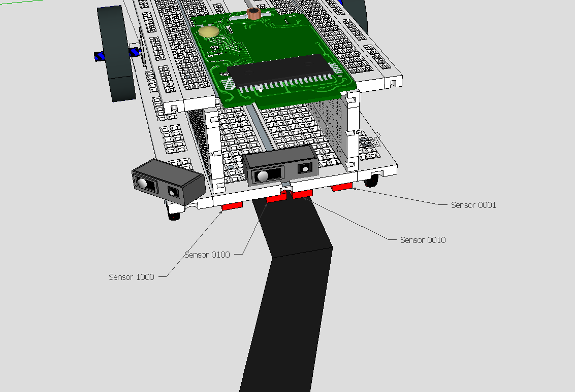
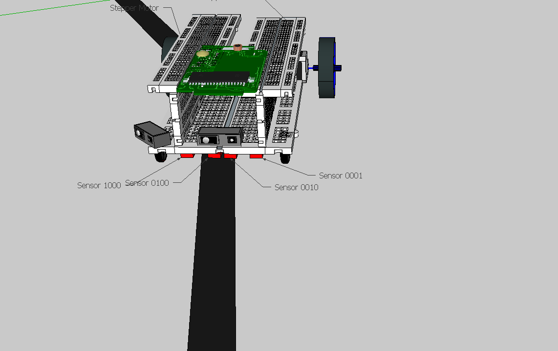
For placement of sensors, it was figured that putting the reflective sensors as far as possible from your pivoting wheels, will give the microcontroller a better reaction time and reduce the chance of overshooting during the line following as well as the artwork trial. Since it allows more time to react. The distance between the sensors depended on the track itself, and in terms where places 1-3cm apart to detect whether there are discontinuities in the track. As for the distance sensors, placing one at a 45° angle at one edge of the chassis and the other facing the front allowed for a better sense of the maze. General placement of the sensors can be seen below.
Electrical Design
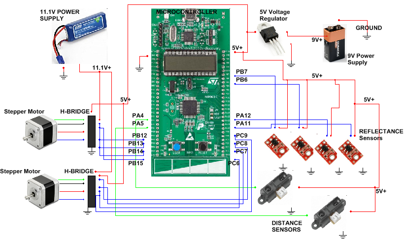
The Electrical Design was pretty intuitive, the schematic design was straight forward and it went hand in hand from what was original planned. The electrical design was a build off from the previous labs. See figure 9 below for the general layout of the electrical system. We took the time to draw a visual schematic that was easy to read and follow and which laid out all the components used to in the system to be controlled by the microcontroller.
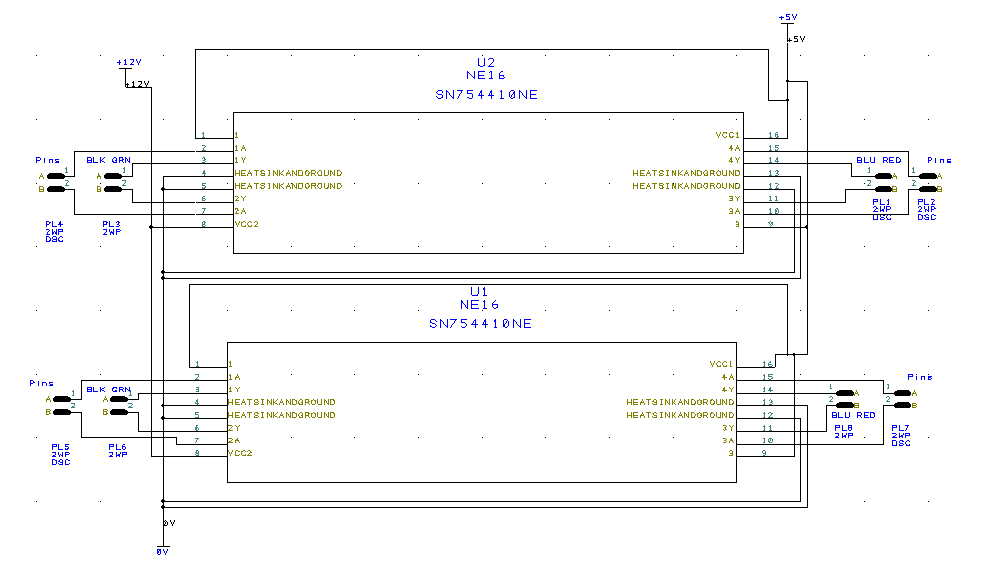
H-Bridges
H-Bridges can be seen on the side of the robot. These are an important part of the system as they help drive the stepper motors foward. As can be seen from the Electrical Design and the image below, they take up most of the wired connections of the robot. In general we utilize at least 8 pins to drive both stepper motors, at least 4 pins for the reflectance sensors, and 2 pins for the distance sensors. That gave us a total of 14 pins used.
Software Architecture
Maze Algorithm
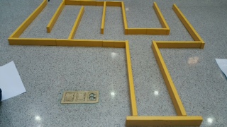
The Maze Conquered
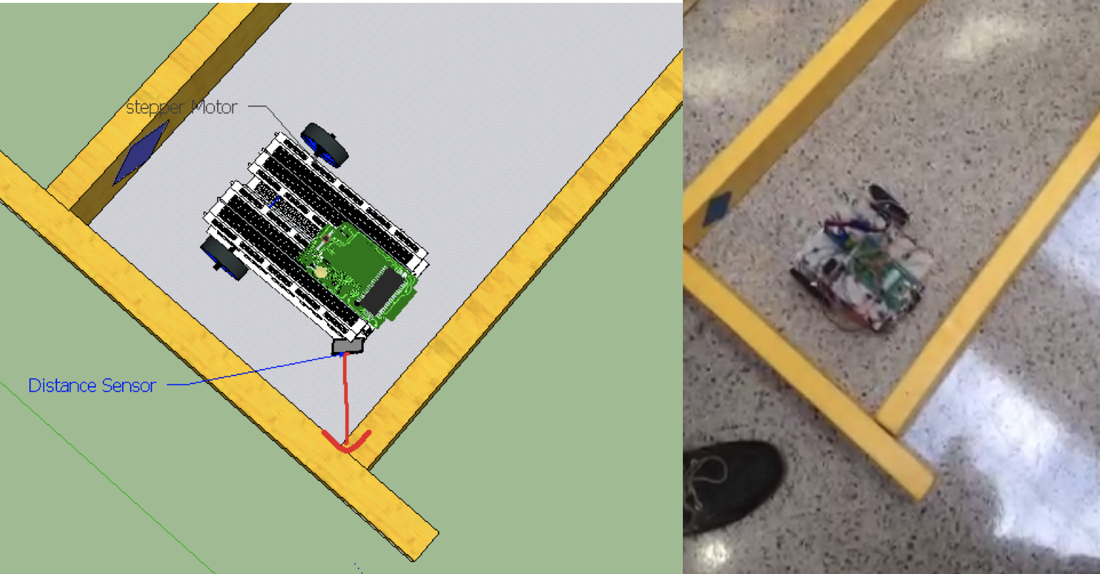
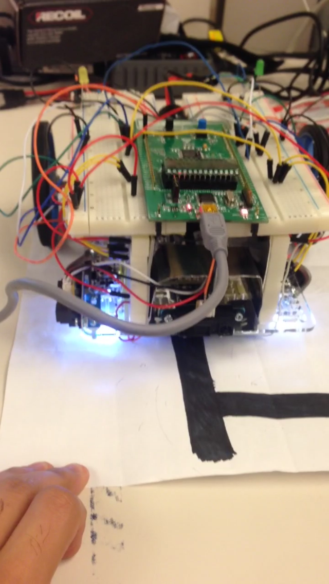
The approach for the algorithm was thinking about how a human could potentially be able to navigate the maze without opening his/her eyes. An algorithm which mimics a right hand on one side of the Maze’s wall. For this algorithm, it was decided to use only one distance sensor at a 45° angle. This proved to be sufficient enough and we were able to come up with a simple algorithm that solved the problem at hand and was successful. The following images demonstrate how the task was accomplished.
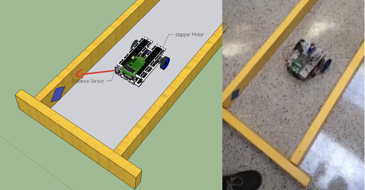
Wall between 10cm and 20cm. The the robot keeps just keeps moving forward.
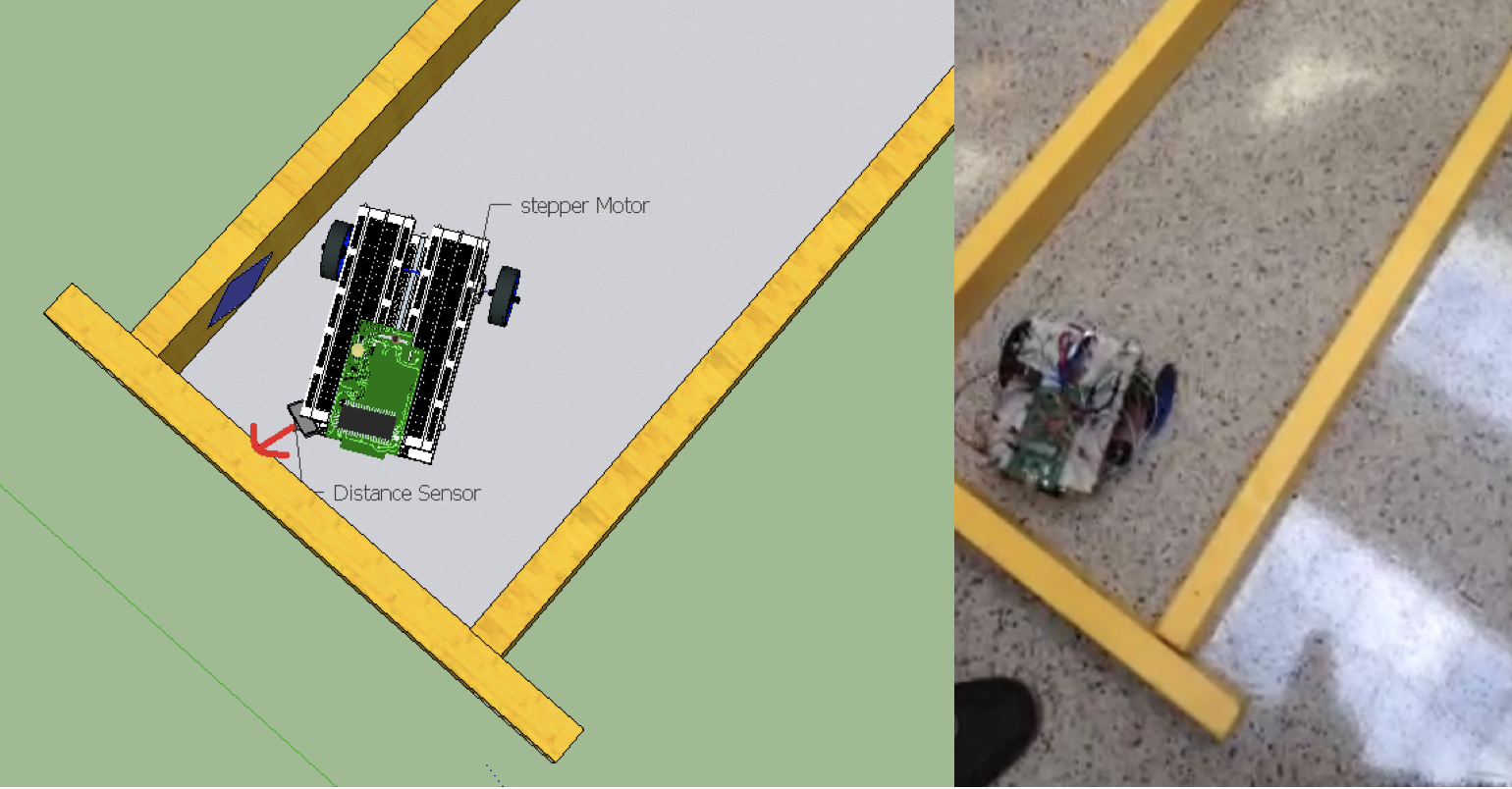
Front wall at a distance less than 10cm. The robot turns left
Front wall at a distance less than 10cm. The robot turns left
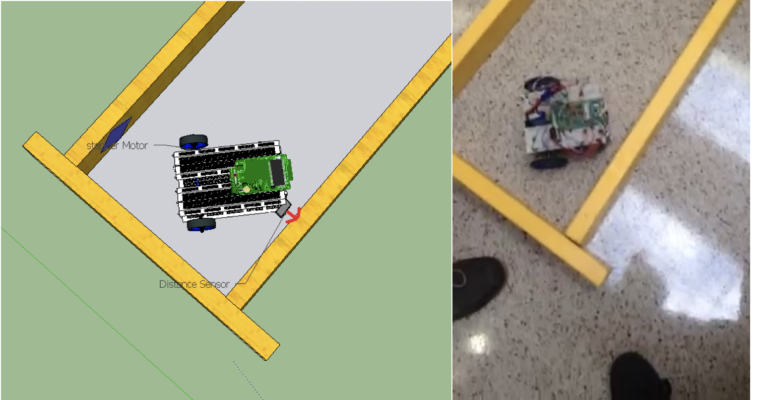
Front wall at a distance less than 10cm. The robot turns left
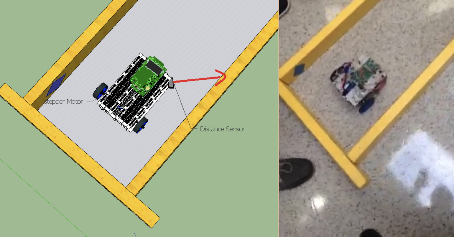
Wall between 10cm and 20cm. The the robot keeps just keeps moving forward.
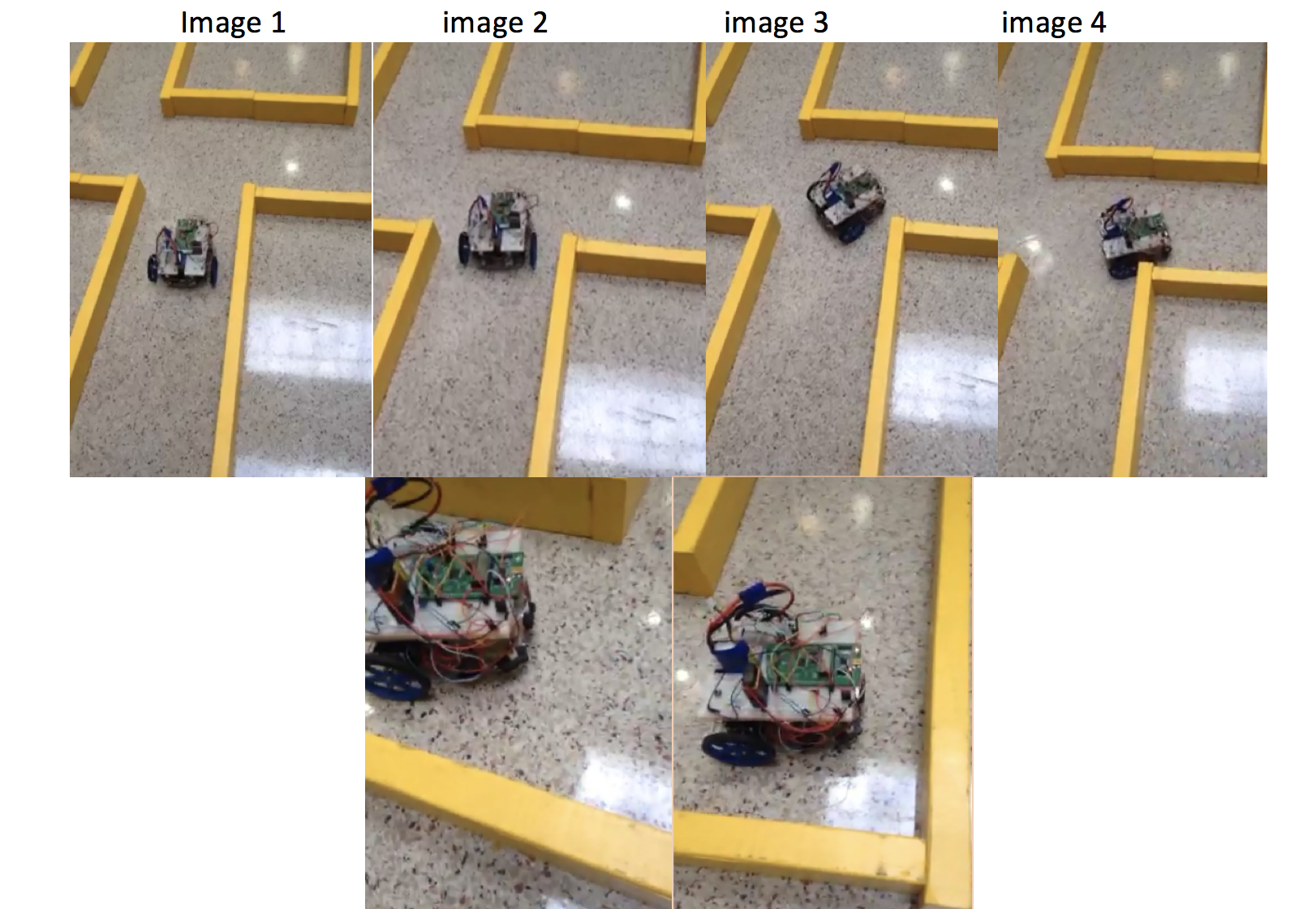
Robot completes the Maze using the logic above
Line Following Algorithm
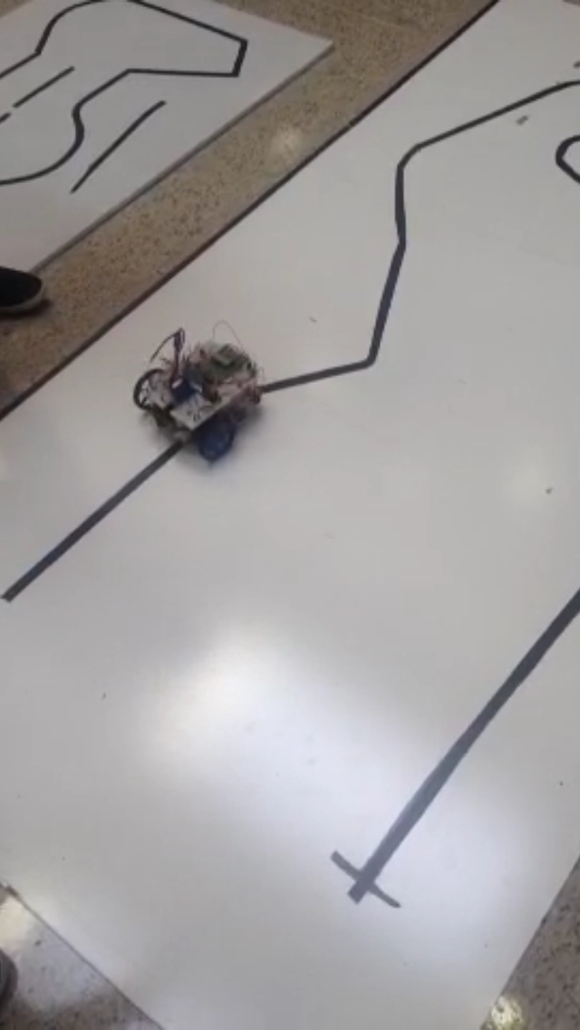
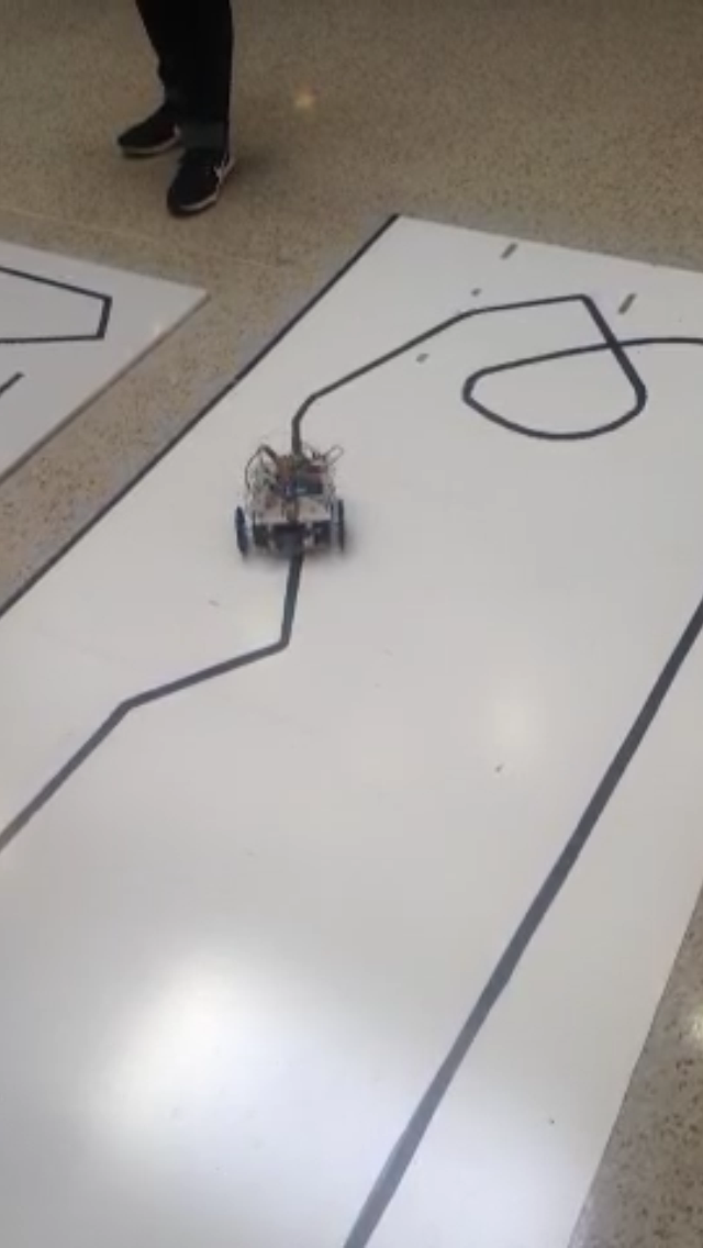
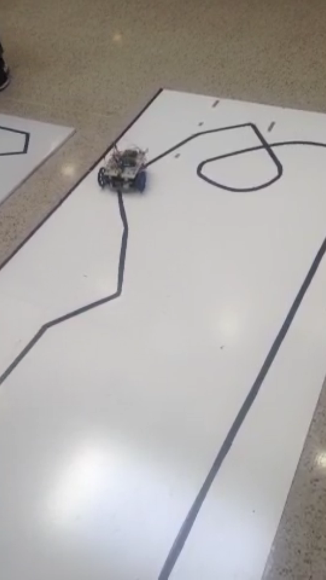
The Line Followed
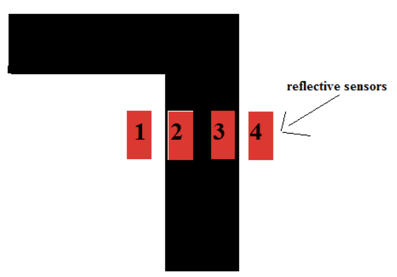
With line following we have two different cases for each of the reflective sensors. It was either black or white , in simpler terms this may just be represented as true or false , ‘1’ or a ‘0’ respectively. We decided to go with 4 sensors to read the line on the floor. These four sensors can be denoted as four binary digits 1111: sensor 1, sensor 2, sensor 3 and sensor 4 respectively. There are just a few rules that the robot had to take in order to be a successful in following the line. As the robot is following the line, it will continue as long as any of the sensors detect a line, that is 16 different possible ways it can see the line. If the robot for any reason leaves view of the line that is 0000, then it baked up slightly. This made sure that the system stayed on the line at all times. The task was to finish. Speed was not a factor we considered.
Testing Reflectance Sensors
In order to achieve what can be seen above, it be broken down into 3 logical steps. As the sensor read the conditions set in front of them the value is stored in a byte with each bit representing the status of one particular sensor. If a bit is 1, then the corresponding sensor is over the line and if the bit is 0, then it is not on the line.
The following examples will make it clear. If the value of the sensors is ‘0110’, or sensor 1=0 , sensor 2=1 , sensor 3=1, and sensor 4=0 respectively then the robot sees the line and move forward. Each sensor represent a hexadecimal value 0x0000 or 0x0101, up to 16 cases total. After it does one case the program loops again and it performs the corresponding case based on the condition from the final_move below. If the sensors read show a configuration to be 0x0001. This runs the corresponding case 0x0001, which triggers a sequence for the motor to move slightly to the right and them move forward slightly.
If the sensor reads 0x0001 , during this case the robot will see the line in its far right and it terms will correct itself and turn right. This can be true for the case in which sees the sensors ‘1100’ or ‘0011’ or even ‘1000’ and ‘0001’. If the most extreme cases ‘1000’ or '0001' are done, that means that is a need for a turn and the robot will turn accordingly. The speed and direction of both motors are adjusted.
Drawing Algorithm
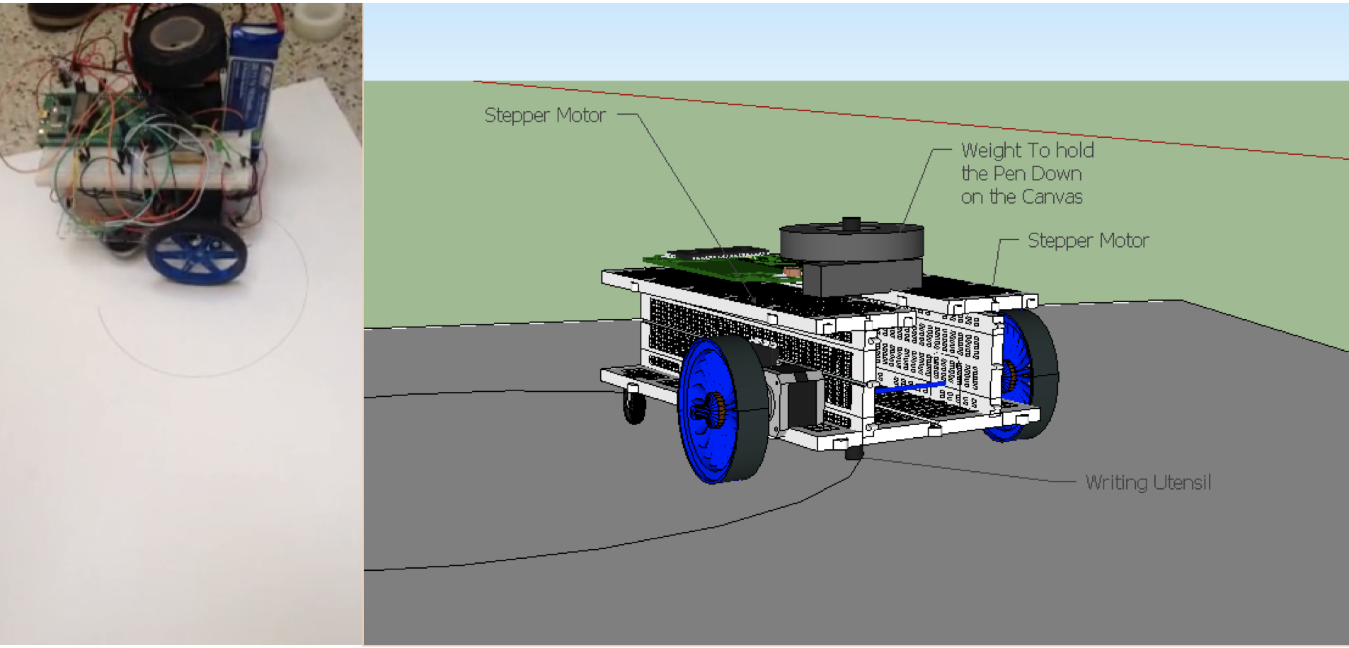
Drawing a Circle on a Canvas
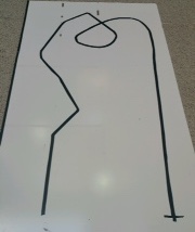
The Writing Mechanism was thought as as a spring in a car, the spring of the pen allowed it to keep constant pressure on the canvas without it being to much pressure. Adding weight on the top of pen, allowed for a small drawing on the canvas.
For qualification, the task was to draw a simple square that was bigger than 9” by 9”, and smaller than 15” by 15”. Ideally a square that is approximately 12”. For the competition the task was to draw a visually appealing image, it was decided that a balloon was the best choice because everyone like balloons. Image above shows the breakdown of the basic components used to achieve the drawing feat.
Although the implementation for the drawing was simple, the build up to achieve such simplicity was not easy, motor function timing , and coordination with the motors and mechanical placement of the utensil made it challenging. But as far as the software implementation in main. It was fairly straight forward. The rest follows the same logic. Different for loop timing and motor direction.
Teammate